This gallery was prepared by Stephen Balter based, in part, on his paper Fluoroscopic Technology from 1895 to 2019 Drivers: Physics and Physiology, MEDICAL PHYSICS INTERNATIONAL Journal, Special Issue, History of Medical Physics 2, 2019
C 1896
01
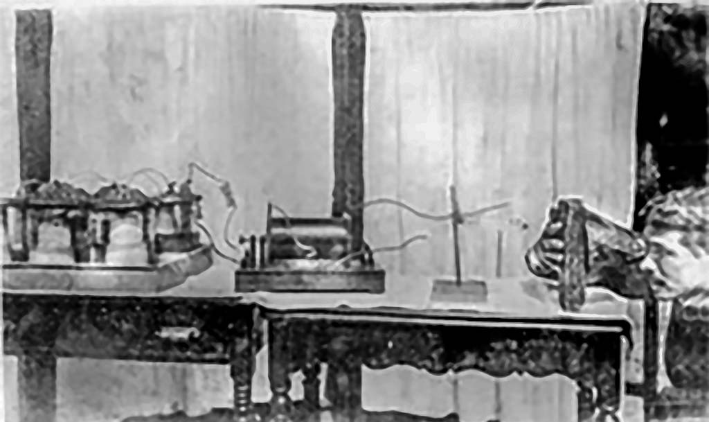
Early fluoroscopy experiments: Physicist’s fluoroscope
Experiments, including fluoroscopy, were reported around the world within weeks of Roentgen’s discovery of X rays in 1895.
The monocular “cryptoscope” is the only item that may not have been immediately available in a typical physics lab following Roentgen’s announcement in 1895.
The investigator is using his own hand as a test-object. There were several published reports of hand injuries before the end of 1896.
Source: Anon
C 1899
02
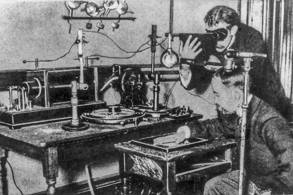
Equipment testing using operators’ hands as test objects
Many early workers used images of their own hands to adjust exposures, with catastrophic consequences.
This ubiquitous photo of a seated individual’s hand is being radiographed while the standing individual is simultaneously using a cryptoscope to fluoroscope his own hand.
This image could be either a posed picture or the fluoroscopist is using his hand as a QA tool while he adjusts the apparatus.
Note the supply of additional X-ray tubes on the far wall.
Source: Anon
03
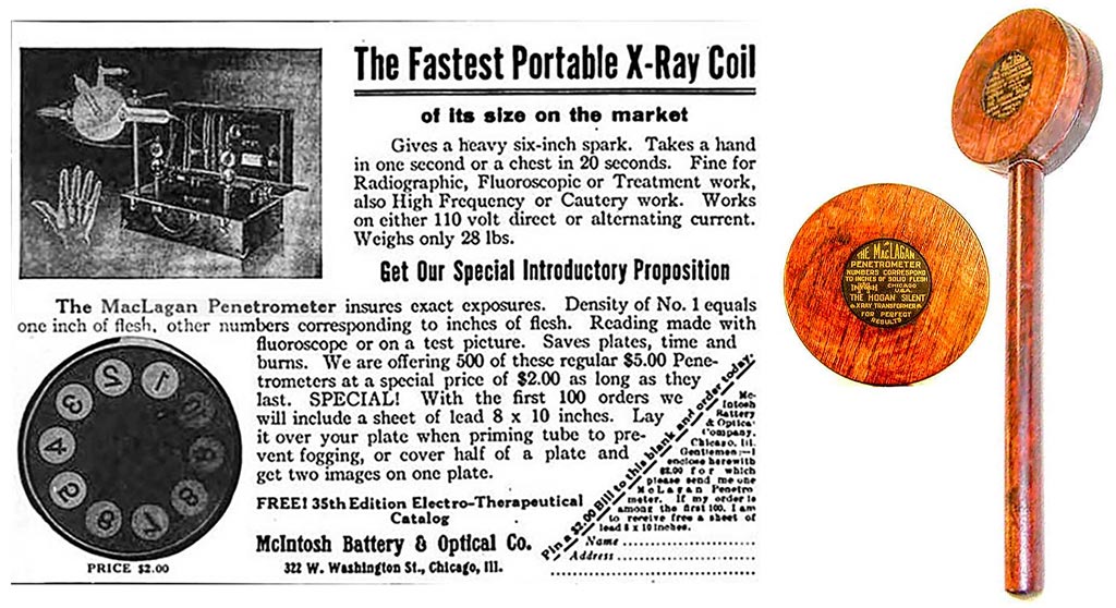
QA using a penetrometer in place of the operator’s hands
This tool allowed technique adjustment without the use of the operator’s hand as a test object.
It is interesting to note that this tool was promoted by an equipment manufacturer.
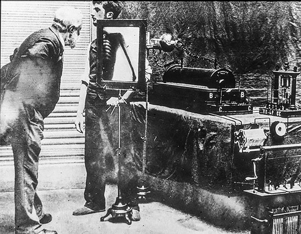
C 1896
04
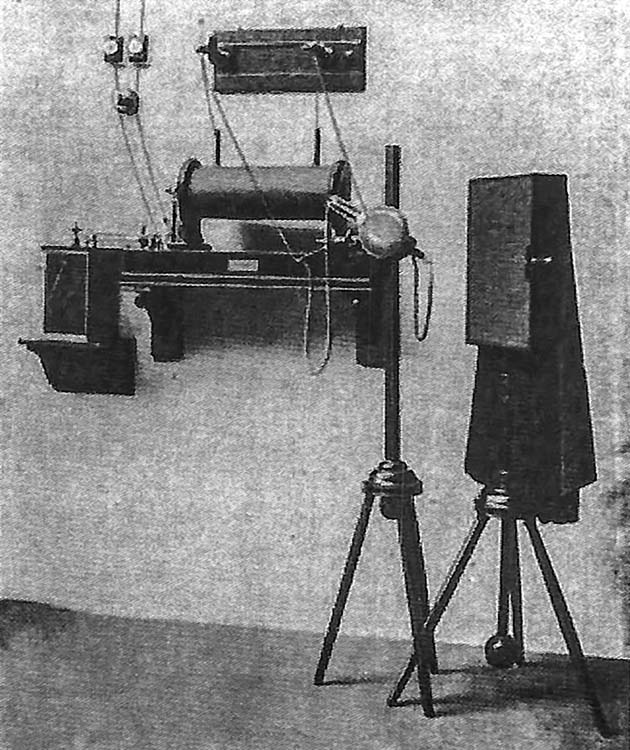
Early complete X-Ray system
The unshielded X-ray tube is just right of center.
There is an attached spark-gap voltmeter mounted on the wall.
The image receptor consists of a large fluoroscopic screen.
A black cloth hood like the hood used with photographic cameras of the era isolates the operator from room light.
This system appears to have been energized by a power line instead of the more common batteries used in this era.
Source: Siemens Healthineers
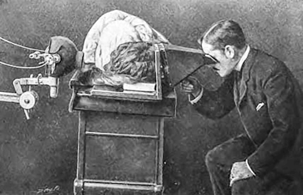
Pre 1900
05
Chest fluoroscopy (original image is heavily edited)
The image of the chest is far too bright to be an unretouched photograph. Also, note that the patient has two left elbows.
Artistic versions of this image were widely available in the early 1900s. Their composition indicates that they were drawn from this ‘retouched’ photo.
Source: Anon
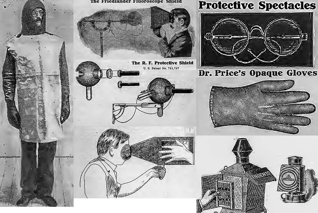
1905
06
Radiation protection devices available by 1905
Personal protective equipment and tube shields were available within a few years of Roentgen’s discovery.
The cryptoscope with a mirror is intended to remove the observer from the X-ray beam (implying the tube shield shown above was also used).
Also, note the image illuminator in the lower right-hand corner of the illustration.
Source: Friedlander catalog No. 3 Public Domain
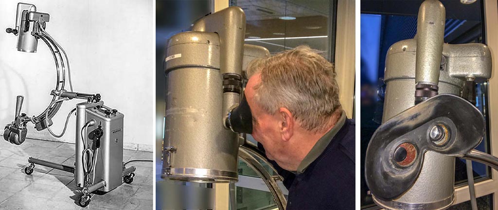
1910
07
Fluoroscopy with a cryptoscope and a partially shielded X-Ray tube
The glass bowl supporting the gas X-ray tube is an electrical insulator.
The X-ray tube in the left image is contained in a glass bowl that appears to have a partial lead shield.
Note the exposed high-voltage wiring.
Source: Tousey 1910 Textbook Illustration
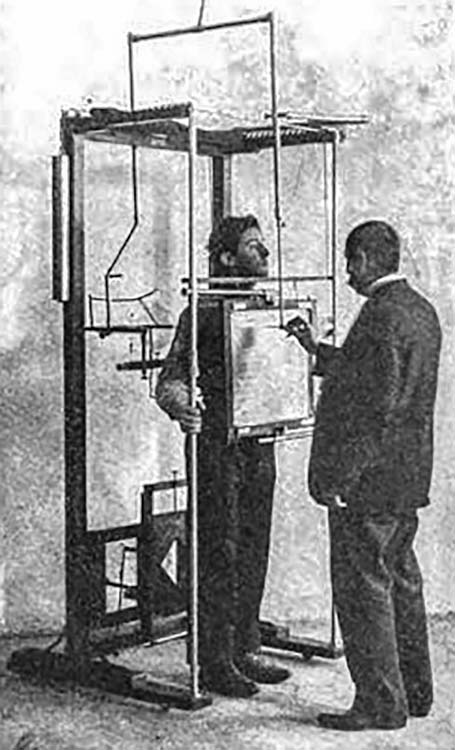
1910
08
Fluoroscopy with a cryptoscope and a partially shielded X-Ray tube
The operator is tracing the patient’s anatomy using live fluoroscopy as the image source.
Captions of this and other figures in the textbook recommend radiography instead of notes or sketches based on fluoroscopy for documentation.
Source: Tousey 1910 Textbook Illustration
C 1916
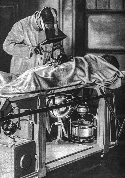
09
Fluoroscopically guided surgery (a form of fluoroscopically guided intervention)
Note the cryptoscope, unshielded X-ray tube, and exposed high voltage wiring.
Room lights appear to be on.
This may have interfered with the surgeon’s dark adaptation.
Source: Anon
1944
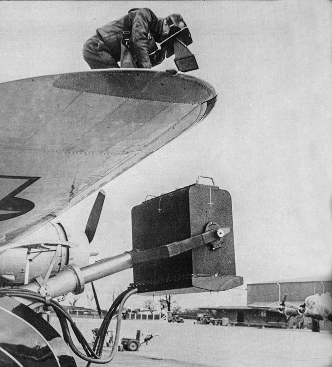
10
WW-2 Fluoroscopic inspection of an aircraft wing
The inspector appears to be wearing radiation PPE, including a face shield built into the cryptoscope.
Based on the size of the X-ray generator housing, the inspection may have been performed in the 100 – 200 kVp range.
Source: Europe – Anon
1926
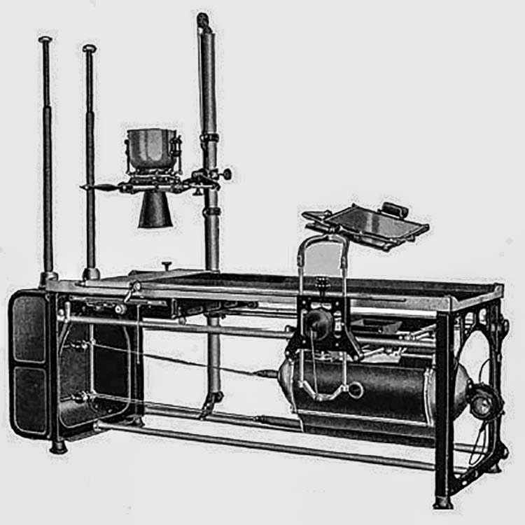
11
Horizontal radiographic/fluoroscopic table
This system includes an over-table radiographic tube (with glass-radiation shielding, a collimator) and an under-table fluoroscopic tube.
The radiographic tube itself and its wiring are not shown in this image. The two poles on the left-hand side are insulators.
In use, exposed high-voltage wires ran from these points to the X-ray tubes.
The enclosure for the under-table fluoroscopic tube may have been provided to minimize stray light during fluoroscopy. Screen fluoroscopy is performed in a dark room.
Source: Anon
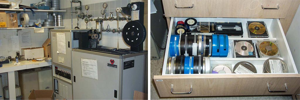
1940
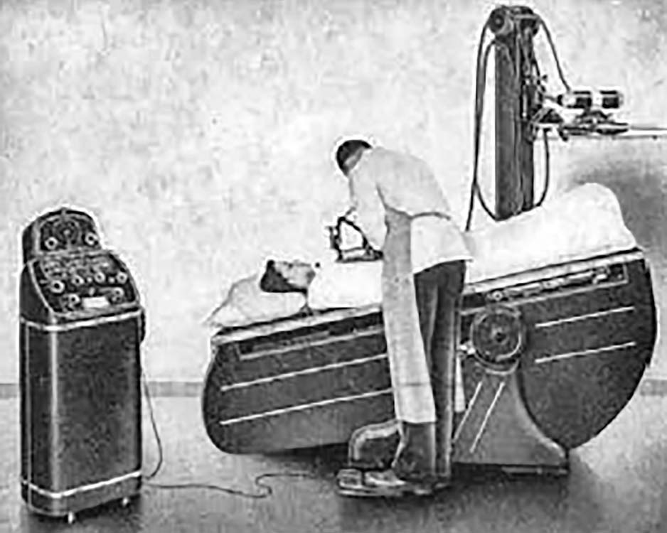
12
Shielded and insulated R/F table
Insulated high-voltage cables replace open wiring.
The X-ray tubes used for such systems were typically shielded by lead contained within a grounded metal casing.
Improved cable flexibility finally provides electrical safety for X-Ray equipment.
Source: PICKER advertisement in RADIOLOGY
1947
13
Chest fluoroscopy with little or no collimation
By this time, the fluoroscopic screen probably had a lead-glass covering providing radiation protection to the operator.
No collimation controls are evident. If collimation was not available, the beam size would have been large enough to fully illuminate the screen in any position.
Note that the screen can slide left to right.
Source: ORAU Health Physics Historical Museum
1955
14
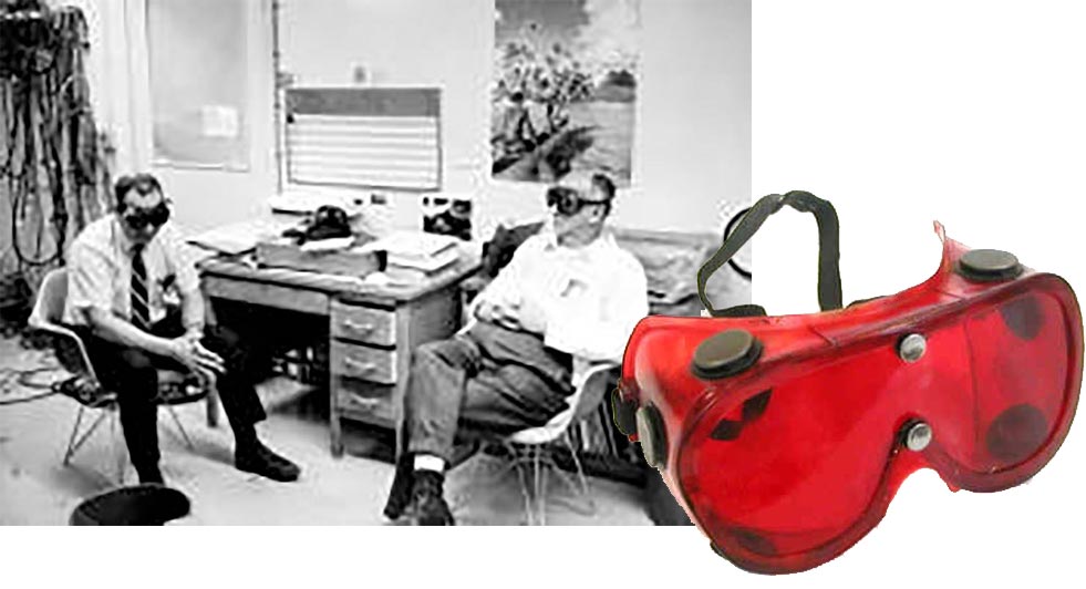
Dark Adaptation
Fluoroscopic screens could only produce a limited luminance at acceptable dose-rates. Operators dark adapted for about 30 minutes in order to fluoroscope at these low light levels.
Typically, they wore red goggles and avoided bright lights during the adaptation time.
Source: Anon
1940
15
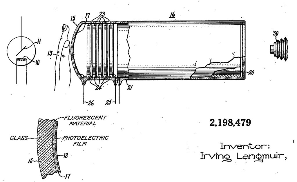
Image Intensifier Patent Drawing
This patent drawing illustrates all the essential elements of an image intensifier except for minification (the output image is the same size as the input image).
It is unlikely that this design entered routine clinical service.
Source: U.S. Patent 2,198,479
16
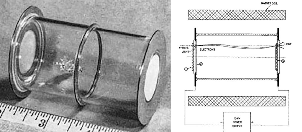
Prototype Image Intensifier (II)
This device has electronic gain but does not utilize minification (input and output are the same size)
The design may have derived from WW-2 night-vision devices.
Source: Coltman 1948
1948 (Top)
17
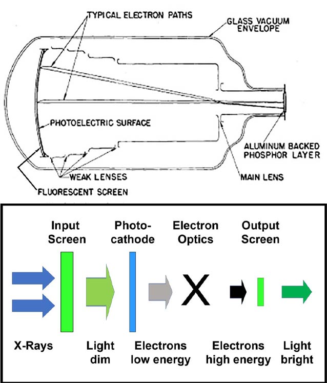
Image intensifier with minification
Minification greatly increased the brightness of the image.
Source: Coltman 1948 (Top)
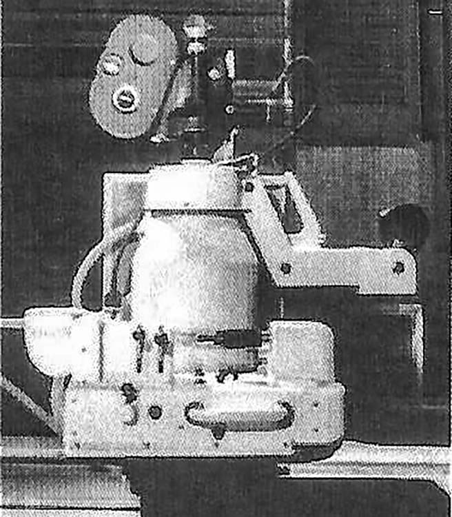
c 1955
18
Clinical 5-inch image intensifier
Note the optical relay lens (on the right) which sent all available light from the II to the monocular viewing optic used by the system.
Source: Philips Healthcare
1956 (left), 2016 (center, right)
19
Mobile 5-inch image intensifier
With image intensifiers, dark adaptation and dark fluoroscopic rooms were no longer required.
Early image intensifiers had brightness gains of a few hundred times that of the brightness of the input screen. To permit operation at normal room light levels, as many of the light photons produced at the output as possible had to reach the observer’s retina. Monocular coupling was provided using optical periscopes.
Image intensifier with cine camera and periscopic viewing
Single output channel for either monocular periscope fluoroscopy or cine-fluorography.
The image intensifier produced enough light to record high dose-rate images on fast photographic film.
Quantum noise was low because of the high dose-rates.
Source: Philips Healthcare
1955 (left), 1960 (right)
21
First generation clinical cardiac imaging fluoroscopes
The 11” II was too bulky to operate above the patient (left).
Note that a monocular viewing system was needed with this tube.
Photo of a ‘pit’ lab shows a 5” over table II with mirror optics added to the setup.
Source: Philips Healthcare
1960(Left), 1964 (Right)
22
Fluoroscopic mirror viewing and analog film documentation
Image intensifier gains improved sufficiently to provide an image to both eyes via a mirror.
Note the backup direct fluoroscopic screen shown on the left.
Note a radiographic spot-film device under the II shown on the left. Analog radiographic film was universally used for documentation of GI and similar procedures in this era.
Source: Philips Healthcare (left), Picker advertisement in Radiology (right)
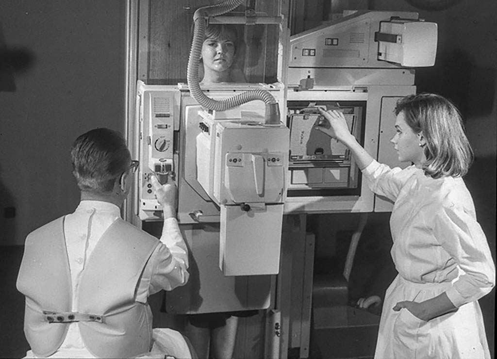
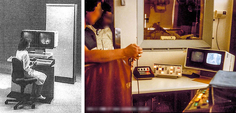
c 1975
23
Video fluoroscopic viewing and analog film documentation
The operator is no longer ‘anchored’ to the image intensifier.
Everyone can now see the fluoroscopic image.
Note both cassette with film/screen and fluorographic acquisition documentation devices.
Source: Philips Healthcare (Left)
1980-1990?
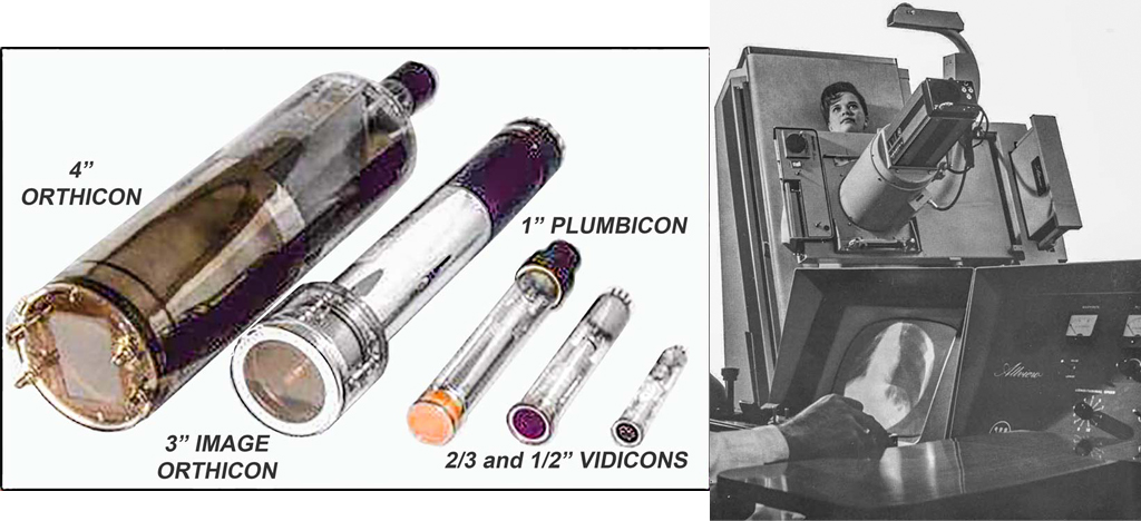
24
Video pickup tubes
Improvements in professional and consumer video pickup tubes were adapted for fluoroscopic cameras.
The orthicon required a great deal of maintenance and was replaced by vidicons when image quality was sufficient.
Source: ANON (left), Westinghouse ad in RADIOLOGY (right)
c 1978
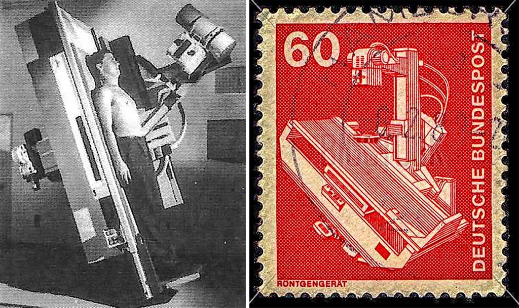
25
Remote control system with under-table image intensifier
Remote control permits procedures with radiation shielding between the patient and operator.
Increased above-table scatter intensity may be a hazard when these systems are used with staff adjacent to the patient support.
These systems have evolved to provide both radiography and fluoroscopy with a single image receptor.
Source: Siemens Healthineers, German Post Office
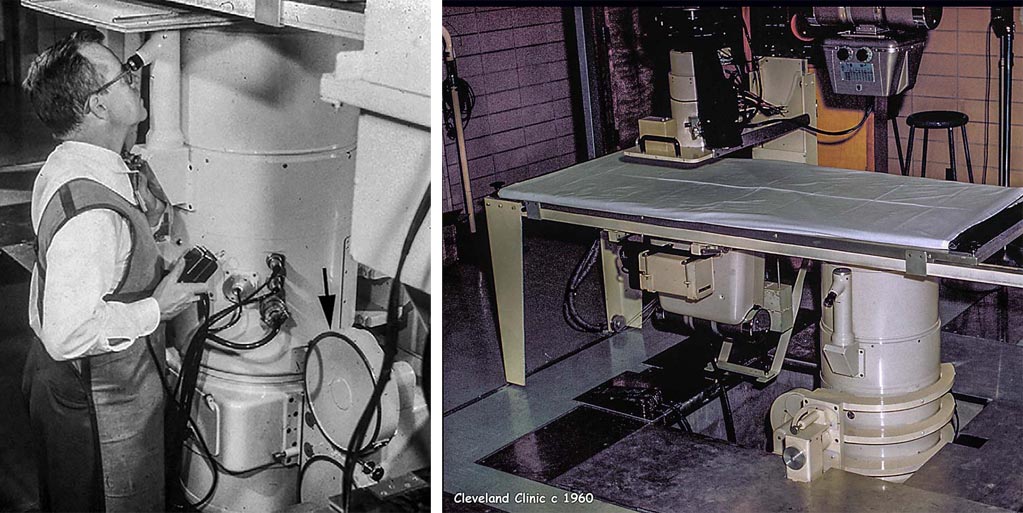
c 1970
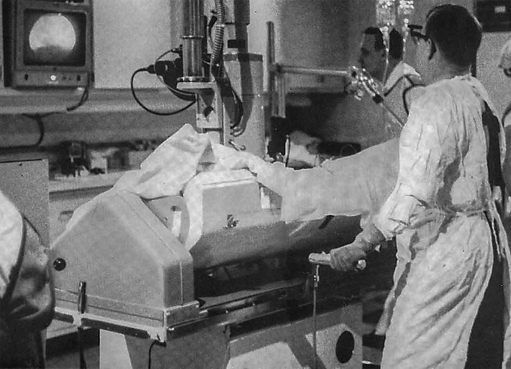
26
Angiographic table with a cradle to rotate the patient relative to the beam.
The cradle was used to rotate the patient into different orientations relative to a fixed vertical X-Ray beam.
The shielded table base was considered an essential element of radiation protection.
Dr. F. Mason Sones, the operator here, and in exhibit 4-21, developed coronary angiography.
Source: Philips Healthcare
1975 (left), 1995 (right)
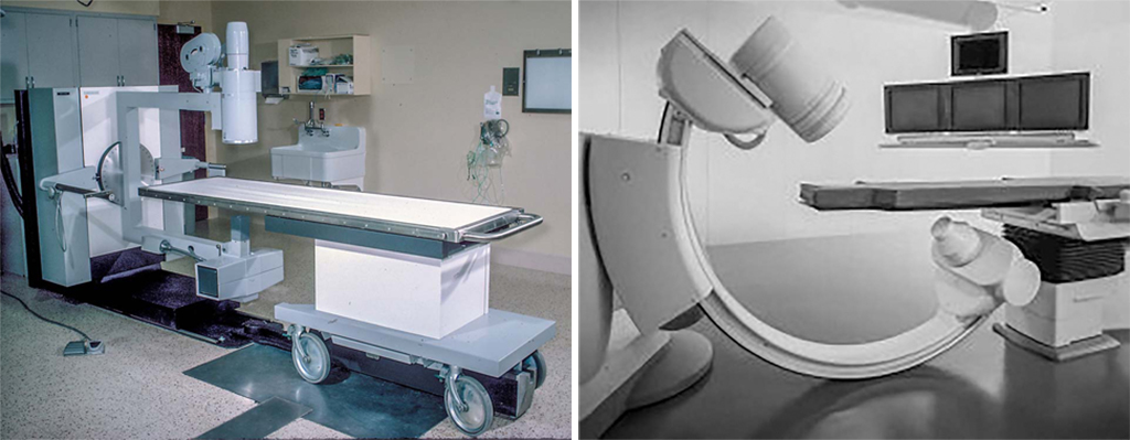
27
Single and dual axis, isocentric rotating X-ray gantries
Single axis (left), dual axis (right).
Moving gantries, and the lack of metal table bases, introduced new concerns about operator irradiation.
These systems provided major improvements in patient comfort and safety by not requiring the patient to be rotated.
Film was needed to provide anatomical coverage beyond the 9” image intensifier used in this era.
This lab has biplane changers for angiography and a separate X-ray tube/II for fluoroscopy.
Variable frame rates provided by the controller during individual sequences were used to optimize the very limited available film supply.
In-run variable frame-rate DSA is available in most modern digital fluoroscopes.
Source: St. Vincent Hospital, Worcester MA (left), Sanchez-Perez Radiology advertisement (right)
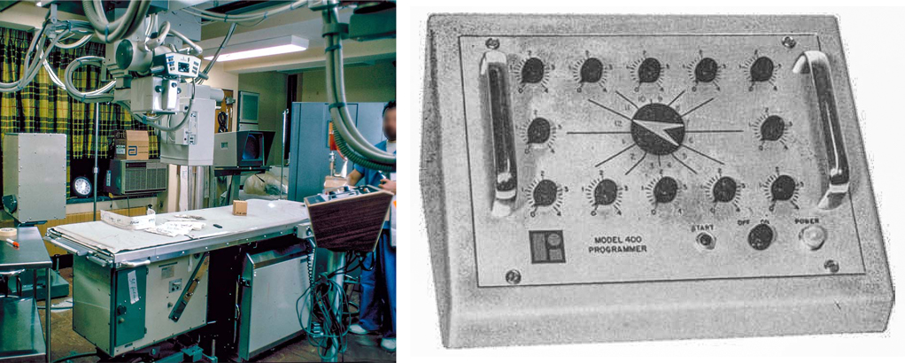
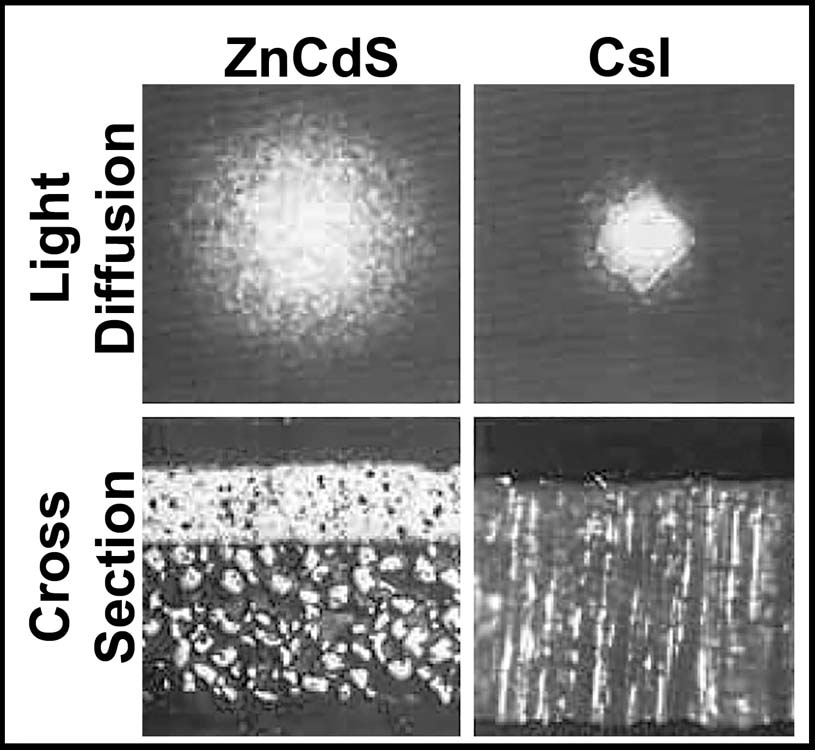
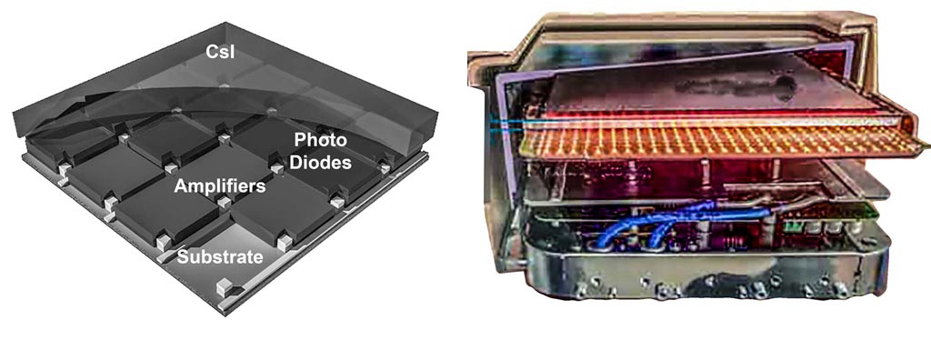
1975
29
Cesium Iodide (CsI) replaces ZnCdS as the image intensifier’s input screen
Replacement of ZnCdS by CsI was a major step.
The crystal needles improved spatial resolution because of less lateral light diffusion.
The solid CsI layer improved DQE because of greater X-ray stopping power.
Source: Philips Healthcare
1980
30
First Generation DSA Systems
Almost all 20th century DSA systems used analog video systems followed by A/D converters. These components were frequently the cause of image quality failures.
The initial generation of DSA used a 256 x 256 matrix because of memory size and temporal bandwidth limitations. Note the size of the electronics cabinet needed to house the image processor.
Source: Siemens Healthineers (left) SB – NYU Hospital (right)
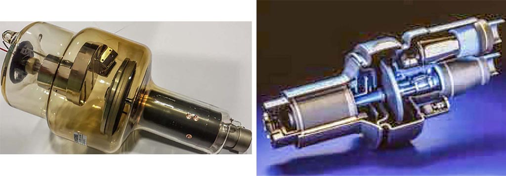
c 1980 (left), c 1990 (right)
31
High cooling rate X-Ray tubes permit spectral shaping of the X-Ray beam
High cooling rates enabled the use of copper spectral filters to better match the X-Ray spectrum to clinical targets. There is enough power to overcome the loss of photons in the filter.
The tube on the left uses radiative cooling.
The tube on the right uses conduction cooling via liquid metal bearings and an external radiator.