13

Treatment Planning and the Development of Modern External Beam Radiotherapy

Computerized Treatment Planning and the Development of Modern External Beam Radiotherapy

This gallery was prepared by Thomas Bortfeld and Colin Orton and is based partly on materials included in presentations at the 2014 AAPM Annual Meeting History Committee symposium by Thomas Bortfeld and Benedick Fraass

Thomas Bortfeld Presentation

Benedick Fraass Presentation


01

1954: First article on computerized treatment planning

02

1959: First efforts to improve treatments using beam modulation

Ken Wright and colleagues used physical absorbers to shape the beam and modulate the beam intensity during rotational therapy in order to reduce the dose to surrounding normal tissues.

This led to development of the so-called “Proimos devices”.

03

1960: Proimos devices

In the 1960s, Basil Proimos devised a number of devices to intensity modulate beams during rotational therapy, such as the spinal shield illustrated.

Both the shields and the patients rotated synchronously.

Some of the Proimos shields were gravity oriented.

04

1966: Multileaf collimators for conformational radiotherapy

In order to shape the beam during modulated radiotherapy with physical shields, Takahashi, from the University of Nagoya, Japan, developed cam-controlled multileaf collimators.

Unfortunately, the Takahashi and Proimos devices were never very successful since they really needed computerized treatment planning to be effectively implemented and this was not widely available until the 1970s.

05

1967: Memorial Hospital Dose Distribution Computation Service

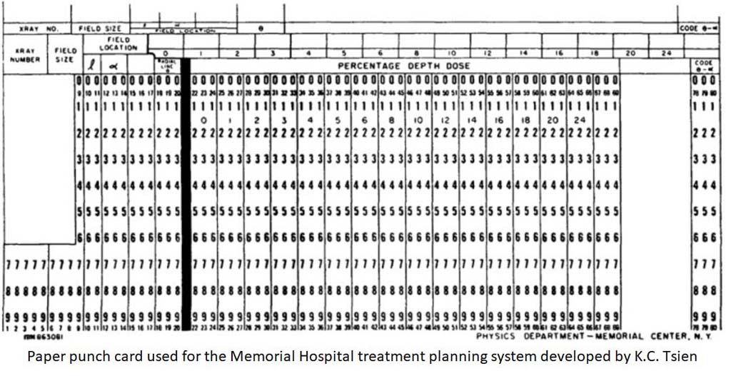
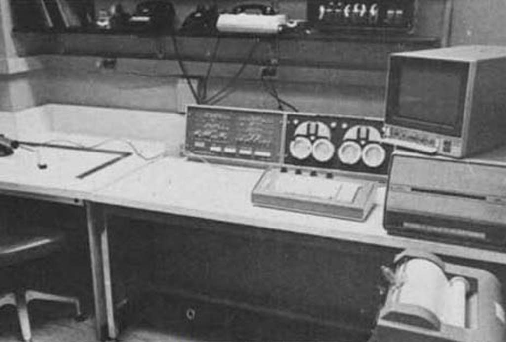
Since most institutions did not have computerized treatment planning, Garrett Holt and colleagues at the Memorial Hospital, New York, built on the K.C. Tsien treatment planning system to develop a Dose Distribution Computation Service for other facilities to use remotely.

Input/output data was transmitted via regular telephone lines to a teletypewriter.

06

1968: First Commercial Treatment Planning System

The 1st commercial treatment planning system was the RAD 8 produced by the Digital Equipment Corporation, Boston.

The core of the system was a 16K PDP 8E minicomputer.

A similar effort in St. Louis, under the direction of Jerome Cox and Bill Powers, led to the production of the programmed console.

Patient contours were entered through a rho-theta device.

Program and data storage on cards with magnetic strips.

Artronix PC-12 treatment planning computer. (From Mohan et al, Radiology, January 1974)
07

1968: The PC-12

The Washington University programmed console led to the production and marketing of the PC-12 by the Artronix Corporation.

System included A rho-theta transducer, keyboard, hard copy unit, storage scope, and digital plotter.

From Fraass (2014)
08

The First Forays into 3-D Planning

The Memorial, RAD 8, and PC-12 treatment planning computers were all developed initially as 2-D systems.

In the 1960s and early 1970s, Ted Sterling, Jan van de Geijn, Jack Cunningham and others began to write the first 3-D treatment planning programs.


These preceded the development of computed tomography (CT) in 1972, and this limited clinical application of their programs.

From Fraass (2014)
09

1972: Development of Computerized Tomography (CT)

Godfrey Hounsfield made 3-D planning feasible when he introduced the CT unit, for which he shared the Nobel Prize in Physiology and Medicine in 1979 (see Significant Advances in CT, Medical Physics 7(4), 1980).

For the next decade, numerous in-house 3-D treatment planning systems utilizing CT images evolved.

From Fraass (2014)
10

1970s: Many in-house 3-D systems were developed

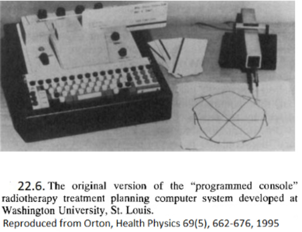
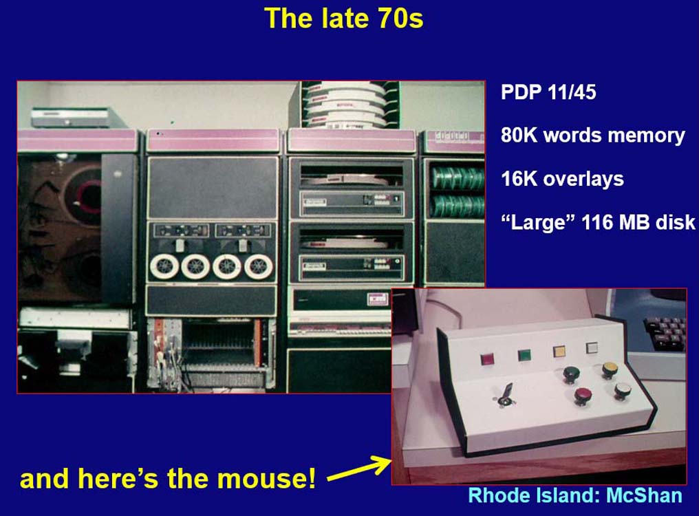
Dan McShan developed one of the 1st 3-D planning systems.

Used interactive color graphics in conjunction with a PDP 11/45 computer.

Shipley et al., JAMA 241(18):1912-1915, 197922.12.
11

1979: Dose-Volume Histograms

The vast amount of data contained in 3D images and 3D treatment plans made it necessary to present information to the user in a condensed form. A tool that is ubiquitous today and has become the standard tool to quantify 3D dose distributions, is the dose volume histogram (DVH).

The DVH was first proposed to quantify the difference between proton and photon treatment plans by Lynn Verhey and Michael Goitein in 1979. It is usually used in the cumulative form, where the y axis shows the proportion of the total volume that receives the dose specified on the x-axis, or more dose.

In this early example shown, the solid line indicates the proton DVH, the dashed line the photon DVH.

From Fraass (2014)
12

1980s: Widespread Use of In-House Systems

A dramatic advancement in 3-D planning was the formation and funding by the NCI, in 1984, of the multi-institutional Collaborative Working Group on the Evaluation of Treatment Planning for External Photon Beam Radiotherapy as one of several NCI contracts established from 1982-89.

Contracts were awarded to:

  • University of Pennsylvania, Philadelphia
  • Memorial Sloan Kettering, New York
  • Massachusetts General, Boston
  • Washington University, St. Louis
13

Use of Computers in Radiotherapy Conferences

Many significant advances in 3-D planning were presented at the International Use of Computers in Radiotherapy conferences during the 1980s.

These conferences have been held every three years, starting in 1966.

The conference in Scheveningen, Netherlands, in 1987 was especially noteworthy

14

1982: 1st proposal for beam intensity modulation with rotational therapy

3-D planning led Lax and Brahme to propose modulating beam intensities with rotational therapy in order to improve dose distributions.

Used to produce a uniform dose distribution in the target volume with the sharpest dose gradient towards organs at risk.

This was intensity modulation in its simplest form, although full-fledged intensity modulated radiation therapy (IMRT) was not possible until the introduction of inverse planning.

15

1988: Inverse planning and IMRT

Anders Brahme and his team in Stockholm developed inverse planning in order to design beam intensity patterns for IMRT.

With conventional planning, beam shapes and monitor units are selected first, and the dose distribution is then calculated.

With inverse planning, the desired dose distribution is specified first, and optimal beam shapes, beam intensity patterns, and monitor units/beam are then calculated to best fit the distribution required.

It was not until several years later, however, with the widespread availability of computer-controlled multileaf collimators (MLCs), that this could enter routine use in the clinic.

Bortfeld et al., PMB 35(10):1423-1434, 1990
16

Late 1980s: IMRT plan optimization

The inverse problem of radiotherapy planning has no exact solution. Inverse planning has therefore been reformulated as a feasibility search or optimization problem.

Early methods to solve this problem included polynomial decomposition (Cormack, IJROBP 13:623-630, 1987), deconvolution (Brahme, Radiother Oncol 12:129-140, 1988), projection methods (Censor & Altschuler et al., IJROBP 16:271-276, 1989), simulated annealing (Webb, PMB 34:1349-1370, 1989) and quasi-Newton methods with penalty functions (Bortfeld & Schlegel et al., PMB 35:1423-1434, 1990).

An early example of uncertainty analysis.
17

1991: Robustness analysis and robust optimization

The highly tumor-conformal  treatment plans achievable with 3D planning and especially with IMRT, are more vulnerable to delivery uncertainties. Treatment planning should, therefore, include uncertainty analysis and error bars.

Michael Goitein has been the lone voice in the wilderness conveying this message for decades before the field started to listen to him.

Uncertainty and robustness analysis has evolved into robust optimization (Unkelbach et al., PMB 63(22), 2018) and was introduced into commercial treatment planning systems (RayStation) in 2014.

Convery and Rosenbloom, PMB 37(6):1359-1374, 1992
18

1992-1993: Delivery of IMRT with a multileaf collimator

In the early days of the IMRT research and development, it was not clear how one could deliver non-uniform beam intensity profiles in a clinical setting. Convery and Rosenbloom devised a method where the leaves of a multileaf collimator move uni-directionally with variable speed while the beam is on. They developed an optimization algorithm to calculate leaf trajectories producing arbitrary intensity profiles with the minimum beam-on time.

A simpler analytical algorithm was developed simultaneously by the groups at Karolinska in Stockholm (Svensson, Källman, Brahme), MSKCC in New York (Spirou & Chui), DKFZ Heidelberg (Stein et al.), and MDACC Houston (Bortfeld & Boyer et al.).

From Bortfeld (2014)
19

Mid-1990s: IMRT technology

With conventional linacs, beam intensity patterns were produced with computer-controlled MLCs with the method described above.

For linacs without MLCs, these could be produced using an add-on Multileaf Intensity-Modulating Collimator (MIMiC).

This was a binary (open/closed) slit fan-beam system, which was computer controlled during rotation therapy.

From Bortfeld (2014)
20

1994/95: First patient treatments with different IMRT technologies

The Nomos MIMiC and Peacock planning system, developed under the leadership of Mark Carol, were used to treat the first patient with IMRT at the Baylor College of Medicine in Houston in 1994.

Cone beam IMRT with MLCs can be delivered by modifying beam patterns with the beam off (Step & Shoot) or with the beam on (with the dynamic MLCs).

The first patient was treated with dynamic MLCs in 1995 on a Varian machine at the Memorial Sloan Kettering Cancer Center.


Bortfeld and Preiser: XII International Conference on the use of Computers in Radiation Therapy, Salt Lake City, 1997
21

1997: Interactive IMRT planning

Even with IMRT, a tradeoff has to be found between covering the tumor target volume and sparing the surrounding normal tissues. A method has been developed in the KonRad planning system to add dose-volume constraints for normal organs (cross in lilac (brainstem), green (integral dose) and yellow (left eye)), and to change them interactively during plan optimization.

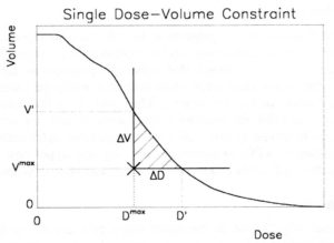
This method has later been adopted by many planning systems, including Varian Eclipse, Tomotherapy, Oncentra Masterplan, and Dosigray.

Interactive IMRT planning evolved into multi-criteria planning on the Pareto frontier with navigation sliders.

22

TomoTherapy and VMAT

In the mid-2000s, TomoTherapy and Volumetric Modulated Arc Therapy (VMAT) were added to the IMRT delivery armamentarium.

Rock Mackie with the prototype Tomotherapy unit
23

2002: Helical TomoTherapy

Helical TomoTherapy was developed since the 1990s at the University of Wisconsin, Madison, by Rock Mackie and Paul Reckwerdt.

Treatments are delivered with the linac rotating around the patient with the binary collimator (Nomos MIMiC) turning segments on and off with the patient translated longitudinally during exposure.

The first patient was treated in 2002.

24

2007: VMAT

A downside of cone-beam IMRT with around 10 fixed beam directions, especially in combination with the step-and-shoot delivery technique, was the long treatment time, which could be 20 minutes or more.

The solution has been a rotational form of IMRT delivery with a continuous gantry rotation. This method has been called Volumetric Modulated Arc Therapy (VMAT) or RapidArc.

It required a plan optimization method that could handle this delivery schema. A successful heuristic was developed by Karl Otto (Medical Physics 35(1):310-317, 2008).