16

Instrumentation Devices and Artifacts

01

Instrumentation

This series shows early Instrumentation used or developed by Medical Physicists for use in medical imaging, radiation therapy and health physics from the collection of the University at Buffalo Museum of Radiology and Medical Physics. Most of the photography is courtesy of Chao Guo and the associated narratives are provided by Daniel Bednarek. Suggestions for additions and corrections are welcome.

02

Wood-Interspaced Radiographic Grid

Scattered radiation from the patient can seriously degrade the radiographic image. This was recognized early and a number of pioneers in radiology had the idea of using a grid of metal strips aligned with the primary x-rays to intercept the deviant scattered rays exiting the patient. Otto Pasche of Switzerland proposed the idea in 1903 and Gustav Bucky obtained a German patent in 1913 for a moving grid, while Drs. Eugene Caldwell and Hollis Potter independently worked on the concept in the United States. In 1915 Potter presented the idea of a rotating grid to eliminate the appearance of grid lines at the American Roentgen Ray Society annual meeting and in 1921 General Electric began to market a laterally moving grid with linear strips of Potter’s design.

The grid shown here was used in the 1920’s. It contains lead strips separated by wood interspaces about 1 mm in thickness. The strips were placed over a curved surface with a radius of curvature equal to the distance to the x-ray tube focal spot so they would be aligned with the diverging primary rays. A pneumatic tube device at the bottom of this picture moved the grid in one direction during the exposure to blur the grid lines. Air in the tube was compressed with much effort by the operator by pulling an attached plunger and was released by pulling a cord just prior to the exposure. The speed was adjusted by turning a knob that controlled the rate of release of air from the pneumatic tube. A tray behind the grid held the film cassette. (From the estate of Edward Eschner, M.D.)

03

Wood-Interspaced Radiographic Grid

04

Upright Stereoscope

General Electric / Victor X-Ray Corporation patent

Stereoscopic viewing of x-ray images was used almost from the beginning of medical radiography. Depth perception is obtained by taking two radiographs of the object with a lateral shift of the x-ray tube, typically by about 10% of the source to image distance. When one radiograph is viewed with the left eye and the other viewed with the right eye, the brain fuses the radiographs into a single image with depth perception or with what some might call 3D viewing. There were many devices developed to aid in viewing stereo-radiographs. This is an upright viewer for full size 35 x 43 cm radiographs that was likely used in the 1940’s, since it has fluorescent tube light panels, but retains the cast iron construction reminiscent of units produced in the 1920’s. Except for the light panels, construction is almost identical to the Victor “Truvision” Steroscope of 1922.  The mirror assembly in the center separates the line of sight of the two eyes and has screw adjustments for proper virtual overlap of the two images. The entire optical bed can be raised or lowered by an adjustable vertical column to accommodate the eye level of the observer. (Donated by Buffalo X-Ray Corp.)

05

Upright Stereoscope

06

Portable Generator with Gas X-Ray Tube, ca. 1915

Scheidel-Western X-Ray Coil Co., Chicago, Illinois, USA

This is a portable x-ray generator and high frequency coil. A gas x-ray tube is shown held by a wooden clamp which allows positioning over the object to be imaged. Bare wires connect the tube by retractable spools to the high voltage source. A rod spark gap allows the voltage to be determined.

The instructions indicate “Never connect this Portable on a direct current without interposing a motor converter for changing the direct current to an alternating current.” The supply voltage range is 104 to 130 volts alternating current.

This unit can be used for x-rays, high frequency treatments, D’Arsonval currents (diathermy), and cautery. Included is a kit of probes and applicators for these purposes. (From the estate of Edward Eschner, M.D.)

07

Portable Generator with Gas X-Ray Tube, ca. 1915

08

Acme Bedside Roentgen Unit

(Acme X-Ray Co, Chicago, Illinois, USA)

First exhibited at the May 1922 meeting of the American Medical Association, this x-ray unit is likely one of the first constructed completely of metal with no wood parts. It includes “a 5-inch, 30 mA, radiator-type tube” in a lead-glass enclosure for shielding. “Control of penetration is secured by means of a 20 point auto transformer. Measurement of penetration is obtained by means of a penetration meter calibrated from 3 to 5 inches.”  The control panel contains a mechanical dial timer, the penetration meter indicating spark gap in inches with penetration controlled by the autotransformer control, a filament control with analog milliammeter and a main switch. The cabinet is mounted on an iron base supported by “rubber tired wheels”. Spring insulating terminals are attached to the upper end of the tube stand to keep the wires to the tube (which are uninsulated) “taut and clear of conducting parts”. [The Journal of Radiology, Vol III, No 12 December, 1922, p. 542.]

09

Acme Bedside Roentgen Unit

10

Wooden Screen-Film Cassette

This screen-film cassette has a finished wooden construction. The closure mechanism is similar to the Halsey Rigidform cassette design with spring-tension, rotating clasps. The cassette includes a single front-sided screen and a felt pad on the backside to ensure screen-film contact. There is no marking on the cassette, but the intensifying screen has writings in traditional Chinese indicating “Aurora” (极光   Jíguāng), which is likely the manufacturer’s name. Also indicated on the backside in Chinese is the screen size of “10 inches by 12 inches”. The wooden construction suggests that this is an early design, ca 1915.

11

Wooden Screen-Film Cassette

12

Sphere Gap Meter

Patented August 28, 1923

Westinghouse X-Ray Company, Incorporated

Long Island City, New York, USA

The electrical potential difference applied across the x-ray tube can be measured by determining the separation of two spheres for which a spark will jump between them.  This sphere gap could be mounted on the transformer cabinet or overhead. A measurement was made before the x-ray exposure to determine the kilovoltage applied across the x-ray tube. As the kiovoltage was adjusted to match the gap separation for the selected kV, a spark was produced between the balls. (From the estate of Edward Eschner, M.D.)

13

Sphere Gap Meter

14

Westinghouse Reliatron Image Intensifier

Early image intensifier tube developed at Westinghouse Research Laboratories near Pittsburg, PA by John Coltman in 1948. The first systems were distributed by Westinghouse as the Fluorex system in the 1950’s. The II slowly replaced the direct view fluorescent screen that was used for fluoroscopy in hospital X-Ray Departments for many years previously. The input phosphor is at the bottom and the output phosphor at the top in this picture; the electrostatic electron focusing rings are seen through the glass sides. (From the estate of Edward Eschner, M.D.)

15

Thorotrast Contrast Medium

Thorium dioxide was sold under the brand name Thorostrast for use as a vascular contrast medium in the 1930’s. It worked well because of the high atomic number of thorium but was unfortunately radioactive and resulted in liver lesions in patients. The association was soon realized and Thorotrast use diminished in the late 1930’s and early 1940’s. (From the estate of Edward Eschner, M.D.)

16

Keleket Eye “Foreign Body” Localizer

A tunnel in the base protects one-half of a 5-7 inch glass photographic plate while the other half is exposed to x-rays. Exposures are made of the head at two specific angles with the plate shifted to expose a different half of the plate for each angle. A double clamping device with cushion pads is used to hold the head in place. The localizer device consists of two fiducial objects with  a ball separated from a cone by exactly 15 mm on the end of an arm; the ball is placed at the center of the cornea of the afflicted eye with the eyes closed and the spring-loaded rod is depressed to retract the ball 10 mm away from the eye. A chart and Dr. Sweet’s method is used to localize the foreign body from the two images on the plate. (Donated by the estate of Dr. Butler)

17

Early Film Viewbox (1930’s)

This viewbox consists of a conical shaped back to provide uniform illumination of the film with a single incandescent blue-tinted bulb on the back side. The arms on the sliding bars originally held black shades that could be used to mask the film to eliminate glare. A glass plate radiograph is in place on the viewbox in this photograph. (Donated by Dr. Edward Eschner)

18

Darkroom Accessories

The early darkroom utilized manual processing. Several of the chemicals used and a timer to determine the duration for each phase of the process is shown in this photograph. (Donated by the estate of Edward Eschner, M.D.)

19

Tagarno Cine Film Projector

Images of the beating heart were recorded in the cardiac catheterization laboratory using 35 mm cinematographic film from the output of an image intensifier. This projector was used by cardiologists to review the film post procedure after film processing. The film could be viewed at different speeds or still frame to allow a diagnosis. Cine film has been replaced by real-time digital viewing and recording since about the year 2000. (Donated by Neil Dashkoff, M.D.)

21

Ritter Dental X-Ray Unit ca. 1921

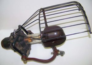
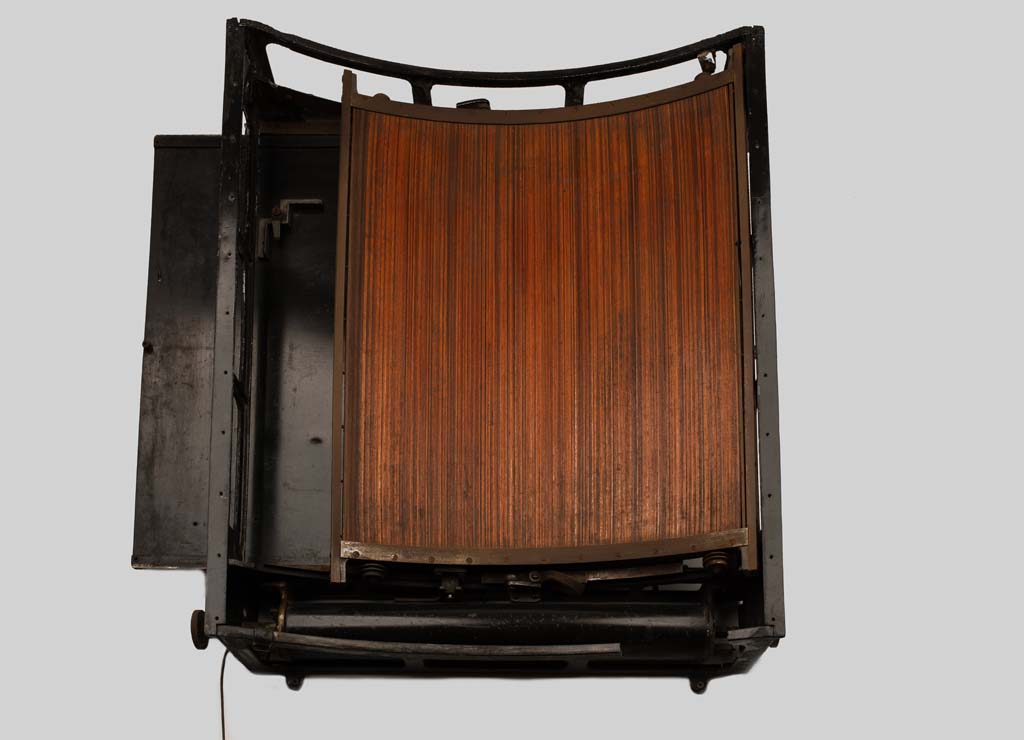
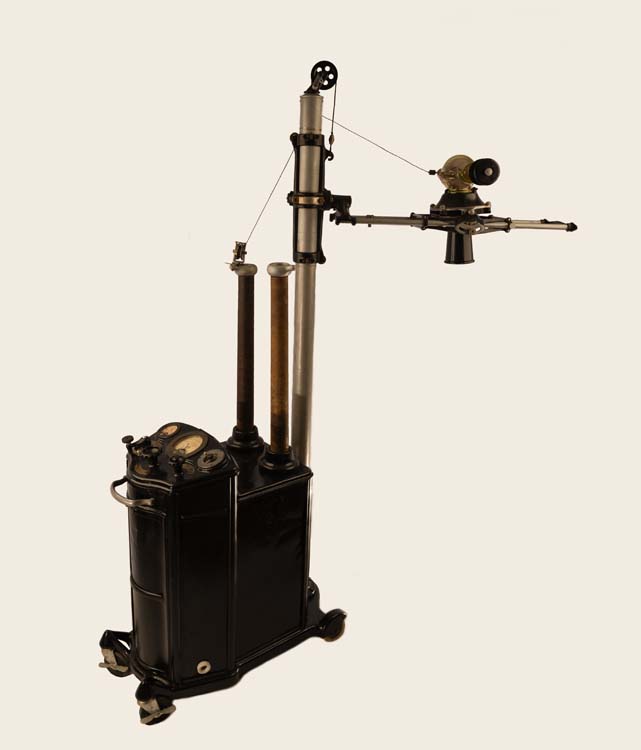
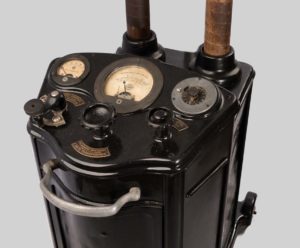
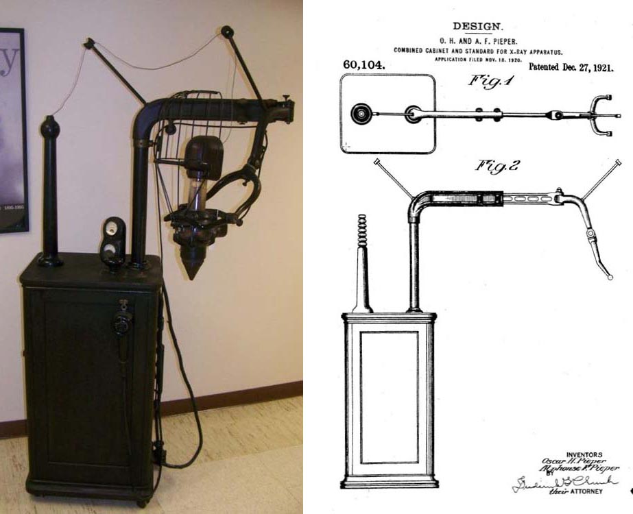
Dental X-Ray machine, manufactured by the Ritter Dental Manufacturing Company, Rochester NY.

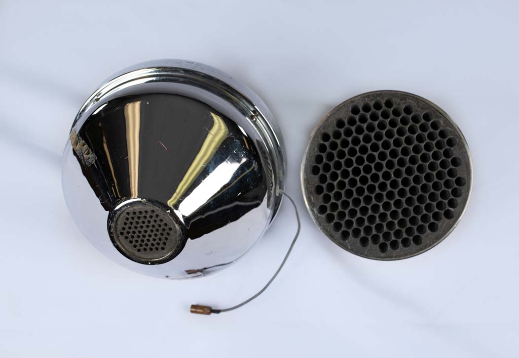
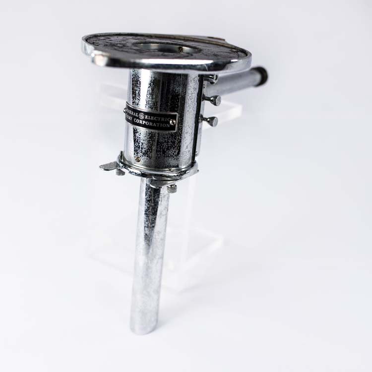
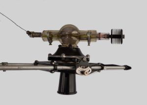
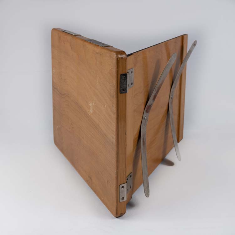
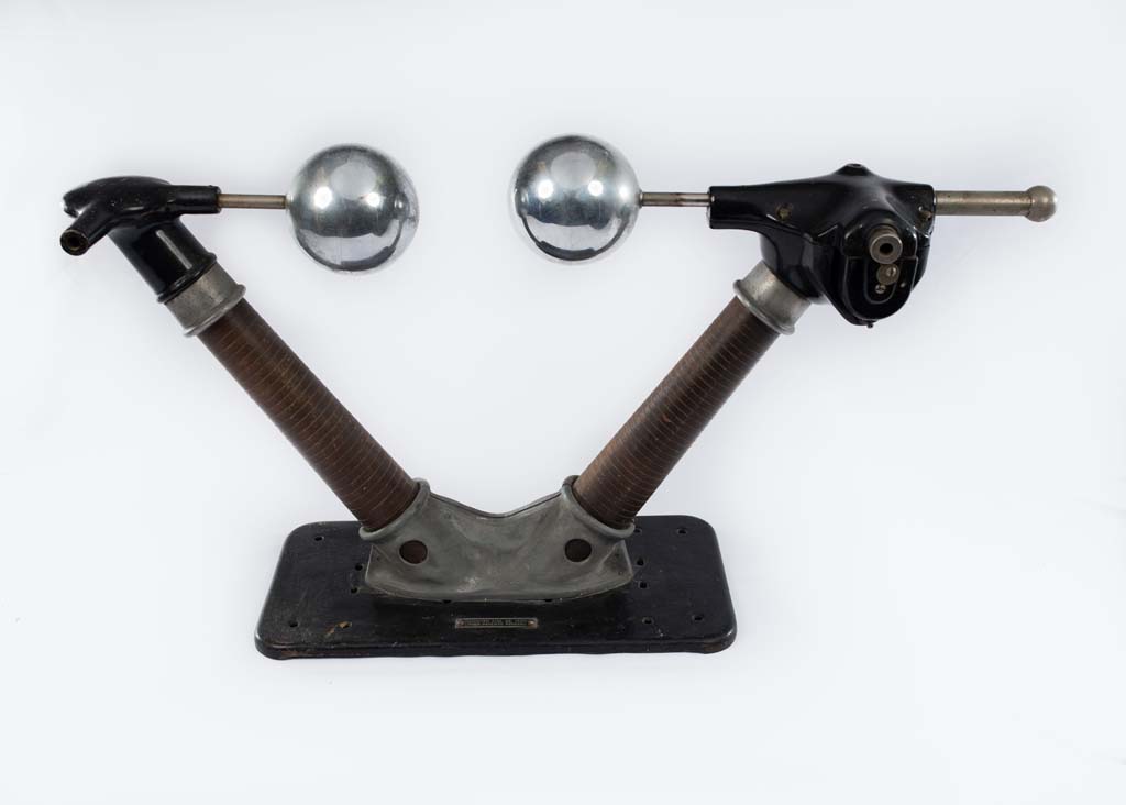
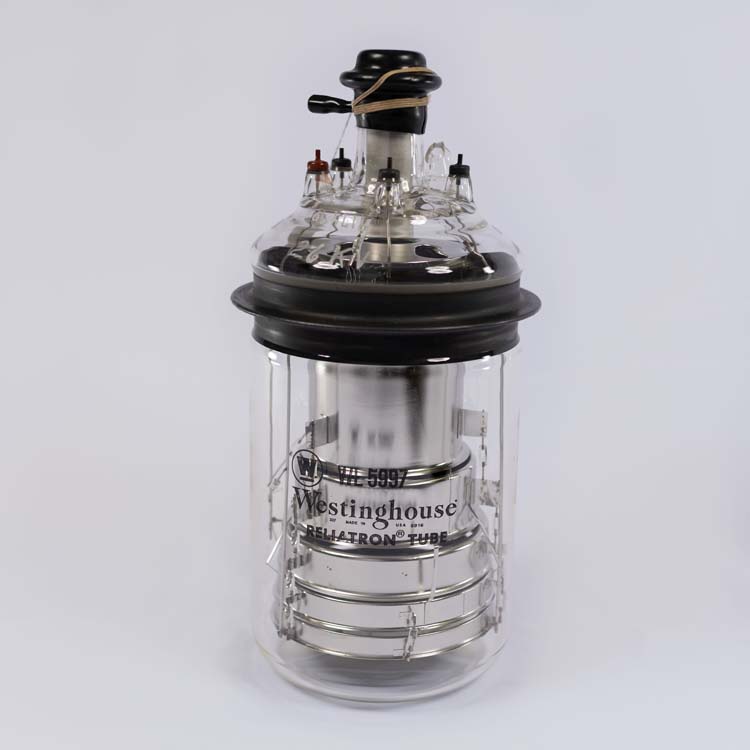
Combined cabinet and standard patented by Oscar H. and Alphonse F. Pieper of Rochester, NY on Dec. 27, 1921 (No. 60104). Base cabinet is wood and contains the transformer and tube control mechanism. The X-ray tube is partially shielded by lead glass and enclosed in a wire cage; a spacer cone is on the output port. (Donated by the University of the Pacific, San Francisco, CA)

20

Eastman X-Ray Film

The Eastman Kodak Company of Rochester, NY was a major supplier of X-Ray film for radiographic applications. This box contained film which was Dupli-tized or which had an emulsion layer on both sides of the film base to increase the sensitivity and typically was used in a cassette containing a fluorescent screen on the front and back sides. Dupli-tized film was introduced in 1913. Safety film, introduced in 1920, had a base of cellulose triacetate which replaced the highly-flammable cellulose nitrate.

(Donated by the estate of Edward Eschner, M.D.)

22

Scharfemessapparat - Sharpness Meter (1930’s)

This instrument was developed in the 1930’s by K. Juris and G. Rudinger from the X-Ray Technology Research Lab at the Vienna (Austria) General Hospital. An x-ray screen-film cassette would be exposed through the device at the bottom, which contained a lead test plate with a large number of small holes. The space between the holes is darkened on the film due to light spreading in the fluorescent screen and the amount of darkening is an indicator of the screen unsharpness. The photometer at the top allows a quantification of the unsharpness using the attached calibration chart. “Efforts to correlate results with this instrument to more conventional measures of unsharpness came to an end with the annexation of Austria by Hitler’s Army in 1938.” (Donated by George Rudinger)

23

Cutie Pie Survey Meter

This radiation survey meter is a Tracerlab, Inc (Boston 10, Mass) Model SU-1B, ca 1950. Its analog scale has a range from 0 to 25 milliroentgens per hour, with a knob selectable multiplier of x1, x10, and x100. The front face has a rotating window that provides unattenuated access to the sensitive volume of the open air ionization chamber. (Donated by the estate of Edward Eschner, M.D.)

24

Rectilinear Scanner Focused Collimator

The rectilinear scanner was the precursor to the gamma camera and allowed a nuclear medicine image to be created by moving a detector in a raster fashion over the patient to build up the image point by point. This lead collimator had many holes that  focused a large 5 inch NaI crystal to a point in the patient. This scanner was used before the widespread availability of Tc-99m and when higher energy photon emitters such as I-131 were used for imaging.

25

Ultrasound Probe Transducers

The transducer on the left is a single element crystal transducer used in the first articulated-arm, compound B-Scan systems. The transducer on the right is a mechanical real-time probe with rotating transducer elements that scan the beam across the field of view.

26

GE Therapy Beam Alignment Localizer

This localizer is attached to the exit port of an orthovoltage x-ray machine to aim the beam at the location of a tumor. The eye piece extending from the side allowed the physician to directly view the placement of the beam prior to exposure; this device was useful for intra-cavitary uterine treatments. (From the former Deaconess Hospital, Buffalo, NY)

27

GE Maximar 100 Superficial Therapy Unit

The Maximar 100 is the 5th design in GE X-Ray’s series of Maximar shockproof x-ray therapy units first developed in 1936. This unit was designed exclusively for superficial rather than deep therapy. It’s kilovoltage range was from 30 to 100 kVp and it allowed a current up to 5 mA. Skin treatments were done at distances of 10 to 30 cm. When operated at 100 kVp, 5 mA and 30 cm SSD with no added filtration, the output was in the range of 1000 roentgens per minute. The tube is immersed in oil and has a beryllium window.  Shown at the bottom are the various cones and filters used  for treatments. The filters range in thickness from 0.25 to 3.0 mm Al  and the two sets of cones allow focal-skin distances of 30 and 15 cm. (Donated by the former Deaconess Hospital, Buffalo, NY)

28

Brachytherapy Nomogram Dose Calculator and Intracavitary Applicators

At the top is a dose calculator for radium interstitial treatments considering distance, source length, Pt encapsulation filtration, source activity and time. At the bottom are intracavitary applicators to treat uterine cancer. (Nomagram donated by the estate of Edward Eschner, M.D.)